Typical bridge circuits with strain gauges
Here the relation between the output signal of the bridge circuit and the strain is summarized.
Call Us
Here the relation between the output signal of the bridge circuit and the strain is summarized.
The Wheatstone bridge circuit is the preferred circuit for measuring resistance. It can be used to determine an absolute resistance or to determine a relative change in resistance. When measuring with strain gauges, the relative change in resistance is measured.
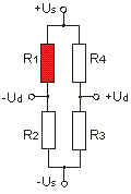 |
Us: bridge supply Ud: bridge output ε : strain k: k-factor (approx. 2,0) Ud/Us = 1/4 · (ΔR1/R1) Ud/Us = 1/4 · k · (ε1) With a k-factor k=2.0 the following applies: 2000 µm/m corresponds 1 mV/V |
The quarter bridge is the most commonly used circuit in voltage analysis.
The active strain gauge (R1) is supplemented by three passive resistors (R2, R3, R4) to form a full bridge.
The bridge circuit with only one active strain gauge does not compensate for temperature-related expansion. Therefore, good "self-compensation" of the strain gauge is required: This is achieved by a negative temperature coefficient of the resistance of the strain gauge. This negative temperature coefficient of the resistance is set so that its magnitude is equal to the change in resistance due to temperature-related expansion, but with a negative sign. Therefore, there are strain gauges with "self-compensation" for steel (thermal expansion coefficient 12 ppm/K) and for aluminum (thermal expansion coefficient 23 ppm/K).
The temperature coefficient of resistance is therefore ideally -24 ppm/K for strain gauges for steel and -46 ppm/K for strain gauges for aluminum due to the k-factor of 2. The temperature response of the resistance (or the indicated strain) due to self-compensation is also called apparent strain.
Due to the self-compensation of the strain gauge, it is not possible to measure the thermal expansion of a material with a quarter bridge. Instead, a second strain gauge R2 with the same properties as R1 is glued to a sample material with an expansion coefficient of 0 ppm/K (e.g. titanium silicate glass) and exposed to the same temperature change as R1. This is then a half bridge. The strain gauges of the same type are glued to two different materials.
To improve temperature compensation, a second strain gauge R2 is glued to a similar material sample in the stress analysis (with the same thermal expansion as the component to be tested). Both strain gauges R1 and R2 must experience the same temperature change (i.e. be installed in the same place). The material sample with R2 (e.g. a steel sheet 25mm x 25mm x 4mm) is elastically bonded to the component (e.g. with silicone).
The nonlinearity of the quarter bridge is negligible for small strains in the range up to 1000 µm/m.
Rule of thumb: At 1000 µm/m strain ("at 1 per mille strain") the deviation of the real strain from the strain determined with the linearized bridge equation is about 1 per mille.
For quarter bridges with an active strain gauge, the use of 3-wire technology is usually required.
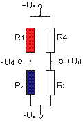 |
Us: bridge supply Ud: bridge output ε: strain k: k-factor (approx. 2,0) Ud/Us = 1/4 · (ΔR1/R1 - ΔR2/R2) Ud/Us = 1/4 · k · (ε1 - ε2) With a k-factor k=2.0 the following applies: 1000 µm/m corresponds 1 mV/V |
In the (active) half bridge, the two active strain gauges (R1, R2) are supplemented by two passive resistors (R3, R4) to form a full bridge. The strain of R1 and R2 must be equal in magnitude but opposite in sign. For example, R1 is glued to the top and R2 to the bottom of a bending beam.
This circuit is used for low-cost sensors. However, a full bridge can be used to achieve twice the output signal.
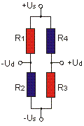 |
Us: bridge supply Ud: bridge output ε: strain k: k-factor (approx. 2,0) Ud/Us = 1/4 · (ΔR1/R1 - ΔR2/R2 + ΔR3/R3 - ΔR4/R4) Ud/Us = 1/4 · k · (ε1 - ε2 + ε3 - ε4) With a k-factor k=2.0 the following applies: 500 µm/m corresponds 1 mV/V |
The full bridge with 4 active strain gauges is the preferred standard circuit in sensor construction. The strains of R1, R2, R3, and R4 are equal in magnitude. The strains of R1 and R3 are opposite to the strains of R2 and R4.
This circuit offers the largest output signal and the best possible compensation for temperature influences and mechanical interference.
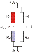 |
Us: bridge supply Ud: bridge output ε: strain k: k-factor (approx. 2,0) ν: Poisson’s ratio (approx. 0.3) Ud/Us = 1/4 · (ΔR1/R1 - ΔR2/R2) Ud/Us = 1/4 · k · (ε1 - ν ε2) With a k-factor k=2.0 the following applies: 1539 µm/m corresponds 1 mV/V |
The active strain gauge (R1) is supplemented by a transversely arranged "Poisson" strain gauge (R2) and two passive resistors (R3, R4) to form a full bridge.
This circuit compensates for temperature-related strain provided that the strain in the direction of the grid of R1 and in the direction of R2 is the same in magnitude and sign.
In fact, this is not the case with cylindrical bodies: the circumferential strain is twice as large as the longitudinal strain. The following applies to the relative volume change: ΔV/V = 2Δd/d + 1Δl/l because V=pi d2/4 l
This circuit is rarely used.
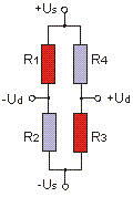 |
Us: bridge supply Ud: bridge output ε: strain k: k-factor (approx. 2,0) ν: Poisson’s ratio (approx. 0.3) Ud/Us = 1/4 · (ΔR1/R1 - ΔR2/R2 + ΔR3/R3 - ΔR4/R4) Ud/Us = 1/4 · k · (ε1 - ν ε2 + ε3 - ν ε4) With a k-factor k=2.0 the following applies: 769 µm/m corresponds 1 mV/V |
The two strain gauges (1,3) in the same direction are supplemented by two strain gauges (2,4) arranged transversely to form a full bridge.
This circuit is preferred for tension and compression rods.
For precision sensors, linearization with additional semiconductor strain gauges is often provided.