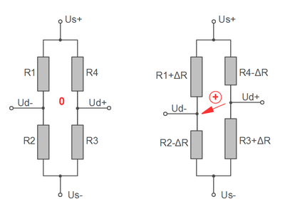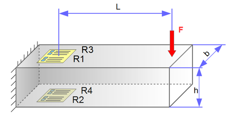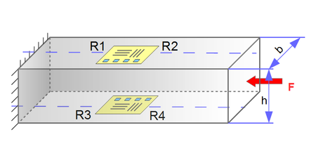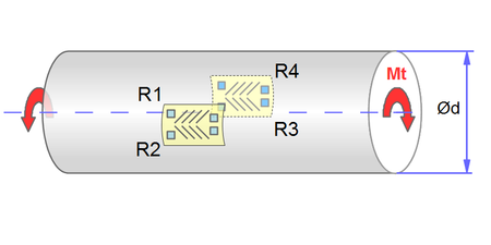
The maximum strain in a torsion bar is less than 45° to the shaft axis. By arranging two measuring grids at +45° and -45°, a bridge circuit with two positively and two negatively strained grids can be realized, similar to the bending stress.
Grid R1 is parallel to grid R3 and positively stretched at right-hand moment.
Grid R2 is parallel to grid R4 and negatively stretched ("compressed") at right-hand moment.
Temperature-related expansion and expansion due to bending or axial force are compensated for with this circuit. Only the torsion is recorded.
The mechanical stress σt results from the torsional moment Mt and the section modulus Wt against torsion:
τt = Mt / Wt
The following applies to the solid cylinder:
Wt = Wp = π d3 / 16
The following applies to the hollow shaft:
Wt = Wp = π (da4 - di4 ) / (16da )
Mt =γ · G ·Wt = ΔUd/Us / k · E/(1+ ν) · Wt
Further information in: kb-festigkeitslehre.pdf
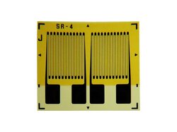
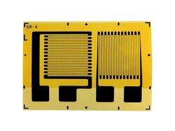
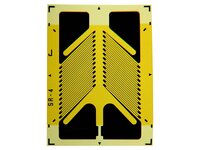
To measure the torsion, strain gauges with a +45/-45 grid arrangement are used.
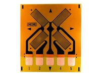
The connection between grid R1 and R2 or R3 and R4 can already be made on the strain gauge carrier, so that only 3 soldering surfaces are required.
A simplified installation, especially for shafts with large diameters (e.g. ship shafts, generator drive shafts) is possible by using a strain gauge full bridge 4x45°
In the case of inhomogeneous stress curves, for example when installing strain gauges at a short distance from splines, the installation of 4 measuring grids on the circumference or 4 double grids in series is recommended.
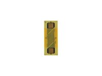
Strain gauge grid for measuring torsion
 |
 |
 |
