Call Us

We are ready to help

Request a special version

Didn't find what you were looking for?
This field cannot be empty.
This field must be at least 3 characters long.

Files

Drag & Drop files here or click to browse

File format supported: (.pdf, .zip, .docx, .png, .jpg .xlsx, .xls, .csv, .txt) & Max Filesize: 25mb

Need to be uploaded up 1 to 3 files.
File format supported: (.pdf, .zip, .docx, .png, .jpg .xlsx, .xls, .csv, .txt) & Max Filesize: 25mb
Leave your details so we can contact you
This field cannot be empty.
This field must be at least 3 characters long.
This field cannot be empty.
Please enter a valid email address.
This field cannot be empty.
Please enter a valid phone number.
This field cannot be empty.
Server error. Try again later.
Thank you!
We will send you a confirmation email and will contact you soon.
Don't have account yet? Register
Back to shopping

Basics of Wheatstone bridge circuit
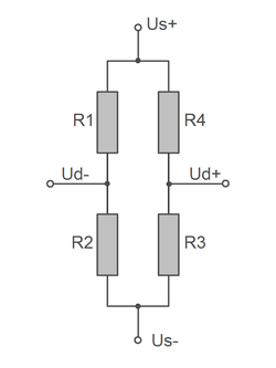


The two connections Us+ and Us- are used to supply the bridge circuit. Us-

The voltage between Us+ and Us- is also referred to as bridge supply voltage Us or bridge supply or sensor input.

Us- is connected to ground GND in many measuring amplifiers.

The voltage change is measured via the terminals Ud+ and Ud- when the bridge circuit is detuned due to strain on one or more strain gauges.

The voltage between Ud+ and Ud- is called "differential voltage Ud" or "bridge output" or "sensor output".

The bridge circuit is balanced (the voltage between Ud+ and Ud- is 0 V) ​​when the following condition is met:

R1/R2 = R4/R3
The bridge circuit is usually powered with a direct voltage of 5V.
2.5V bridge power or 1.0V bridge power are also common if, for example, a low-resistance strain gauge (DMS) with 120 ohms is used, or if the strain gauge is glued to a non-conductive material, so that strong self-heating of the strain gauge must be prevented.


Bridge equation

By applying the knot and mesh rule, we get to the bridge equation:

Ud/Us = R1/(R1 + R2) - R4/(R3 + R4) (Equation 1a)

Linearized form of the bridge equation

For small changes in the differential voltage Ud, the linearized form of the bridge equation can be used:

ΔUd/Us = 1/4 (ΔR1/R1 - ΔR2/R2 + ΔR3/R3 - ΔR4/R4) (Equation 1b)

Relation between resistance change and strain

The relation between resistance change ΔR/R and strain ε is described by the k-factor of the strain gauge.

ΔR/R = k · ε (equation 2)
The strain of an electrical conductor also results in a change in the cross-section of the electrical conductor. The change in the cross-section of the electrical conductor is in turn associated with a change in the electrical resistance.

The condition that when a conductor is "elongated" (positively stained) its volume remains constant results in a "constriction" of the conductor. Conversely, when it is "compressed" (negatively strained) the conductor "thickens".

This purely geometric effect leads to a linear relationship between resistance change and strain under the condition of constant conductor volume:

The proportionality factor is called the k-factor of the strain gauge. For alloys whose volume remains constant under strain (and this applies to all electrical conductors), the k-factor is 2.

1 ‰ strain corresponds to 2 ‰ change in resistance, or
1000 µm/m elongation corresponds to 2 ‰ change in resistance, or
1000 E-6 elongation corresponds to 2000 E-6 change in resistance

Relation between strain and bridge output

The relation between relative bridge output ΔUd/Us and strain follows from equations (1) and (2):

ΔUd/Us = 1/4 k (ε1 - ε2 + ε3 - ε4) (Equation 3)
For a quarter bridge with only one active strain gauge R1, because ε2 = ε3 = ε4 = 0, the following applies:
ΔUd/Us = 1/4 k ε1 (Equation 4a)
 

From equation (4a) we get the relationship between the reading ΔUd/Us and the strain ε for a quarter bridge:

ε1 = ΔUd/Us 4/k (equation 5a)


With a k-factor of 2.0, a reading Ud/Us of 2.0 mV/V (= 0.002 V/V = 2.0E-3) means:

0.002 · 4/2.0 = ε1 = 0.004 = 4‰ = 4000 µm/m
2 mV/V therefore correspond to 4000µm/m strain for a quarter bridge with a k-factor of 2.

The output signals of the bridge circuit with quarter bridge, half bridge and full bridge are summarized on this page:

strain gauge bridge circuit


For a full bridge with 4 active strain gauges (with ε1=ε3=-ε2=-ε4 = ε) the following applies:

ΔUd/Us = k ε (equation 4b)
From equation (4b) we obtain the relationship between the display ΔUd/Us and the strain ε for a full bridge:

ε = ΔUd/Us / k (equation 5b)

Task of a measuring amplifier

The (relative) change in the bridge output ΔUd/Us is usually less than 0.1%. With a 5V bridge supply voltage, voltages Ud of -0.5 to +0.5 millivolts must be measured. A measuring amplifier is therefore used.
The measuring amplifier has several tasks:

  • it provides a bridge supply voltage Us with the highest stability,
  • it amplifies the differential voltage Ud and converts it into a suitable display value.

In the basic setting, a measuring amplifier usually shows the relative bridge output ΔUd/Us. The unit of the display is therefore mV/V.

By standardizing the bridge output Ud to the supply voltage Us, the display values ​​on measuring amplifiers with different supply voltages Us can be directly compared.

Advantages of displaying in mV/V

  • When displaying the absolute bridge output Ud, an additional indication of the supply voltage used would always have to be given,
  • To calculate the strain, only the knowledge of the relative bridge output Ud/Us is required,
  • By calibrating the strain gauge measuring instruments in mV/V, the measuring amplifiers from different manufacturers with different bridge supply voltages are interchangeable

The bridge equation also contains relative resistance changes ΔR1/R1.

The strain is also a relative quantity Δl/l0 


Derivation of the bridge equation for the Wheatstone bridge

wheatstone-bruecke.pdf

wheatstone-bridge_en.pdf
bars-filter