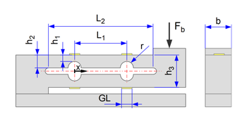
Double bending beam
The double bending beam is a frequently used design element for force sensors. Common names for products with double bending beams are ‘single-point load cell’, ‘load cell for eccentric load’, ‘platform load cell’. Typical applications for double bending beams are platform scales. Here, a load cell is mounted in the centre under a weighing plate.
The main advantage of the double bending beam compared to the single bending beam is that changes in the lever arm have no influence on the elongation. The measuring range is independent of the force application point.
In precision mechanics, the design is known as a parallel spring guide or parallelogram spring guide. The main advantages are parallel guidance and freedom from play, freedom from friction and freedom from maintenance and wear. The disadvantage is the short travel compared to a parallelogram guide (four-bar linkage).
When using the parallelogram spring guide for force sensors, however, the low deflections are an advantage: the stiffness and natural frequency of the force sensor should be as high as possible in order to minimise oscillation of the measurement signal and keep it at a high frequency.
Double bending beam calculator
The calculator calculates the required beam height h1 on the measuring grid for a given force and a given output signal of the Wheatstone bridge.
Further input variables are
- Distance L2 of the measuring grids
- grid length
- k-factor
If the radius r is set to zero, a continuous parallelogram spring without stiffening between the measuring grids is calculated (h1 = h2).
The calculator also calculates the maximum elongation under the measuring grid and the position of the maximum elongation.


