Call Us

We are ready to help

Request a special version

Didn't find what you were looking for?
This field cannot be empty.
This field must be at least 3 characters long.

Files

Drag & Drop files here or click to browse

File format supported: (.pdf, .zip, .docx, .png, .jpg .xlsx, .xls, .csv, .txt) & Max Filesize: 25mb

Need to be uploaded up 1 to 3 files.
File format supported: (.pdf, .zip, .docx, .png, .jpg .xlsx, .xls, .csv, .txt) & Max Filesize: 25mb
Leave your details so we can contact you
This field cannot be empty.
This field must be at least 3 characters long.
This field cannot be empty.
Please enter a valid email address.
This field cannot be empty.
Please enter a valid phone number.
This field cannot be empty.
Server error. Try again later.
Thank you!
We will send you a confirmation email and will contact you soon.
Don't have account yet? Register
Back to shopping

Evaluation of crack measuring strips

The spread of a crack can be detected electrically using a crack measuring strip.

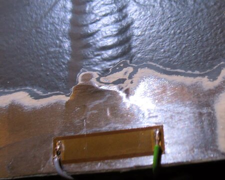
The crack measuring strip “1-RDS22” from HBM consists of individual conductor tracks connected in parallel. It is glued over the end of the crack so that more tracks are gradually separated as the crack progresses.

The resistance of the crack gauge increases gradually as the crack propagates.

Circuit techniques for the evaluation of crack measuring strips

To measure the electrical resistance of a crack gauge, the following are suitable:

  • Resistance measuring bridges,

  • voltage dividers,

  • strain gauge measuring amplifiers.

Anyone who deals with stress analysis usually has a strain gauge measuring amplifier to hand. Therefore, there is a desire to connect a crack measuring strip to the measuring amplifier, although the use of a voltage divider or a resistance measuring bridge would be a less complex solution in terms of measurement technology.

Crack measuring strip RDS-22

The crack measuring strip “1-RDS22” consists of 50 bars, each with a resistance of 44 ohms. In its original state, the connection resistance is therefore 0.8 ohms. It increases according to an e-function from 0.8 ohms to 44 ohms, and finally “infinitely” when the last bar is severed.

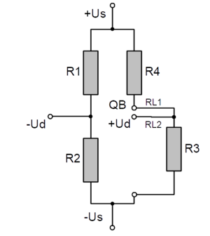
If a strain gauge measuring amplifier is used, it is advisable to connect a variable resistor "R3" using three-wire technology (Figure 1). The resistors R1, R2 and R4 are part of the measuring amplifier, e.g. as a bridge extension.

Figure 1

The resistors R3 and R4 as well as R1 and R2 must be matched to one another. As a rule, strain gauges with a connection resistance of 350 ohms are used. The additional resistor R4 then also has 350 ohms. The ratio of the resistors R1 to R2 only has to correspond to R4/R3. As a rule, they will also have 350 ohms.

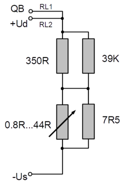
Resistor network for RDS22

The RDS22 with variable resistance from 0.8 Ohm to 44 ohm is connected to R3 as an active quarter bridge.

To utilize the measuring range of -3.5mV/V to +3.5mV/V of a standard strain gauge amplifier, the resistor network shown in Figure 2 is recommended.

Figure 2

A precision resistor of 350 Ohm with a low TK of e.g. 1...10 ppm/K is detuned to about 346.8 Ohm by a shunt resistor of 39K.

As a crack spreads, the resistance increases gradually to 354.3 ohms.

This corresponds to a bridge detuning of -2.3m/V to +3.1mV/V.

When the first bridges are opened, there is a sudden increase in the bridge detuning of about 0.01 mV/V. These jumps are clearly enough to be recognized by a thermally induced drift (e.g. due to the Tk of the 350 Ohm resistor).

bars-filter