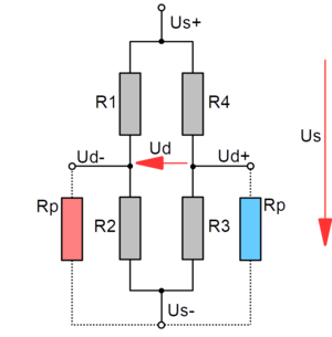
Nonlinearity of the bridge circuit
When calculating the shunt resistance in Equation 5, the linearized form of the bridge equation was used:
ΔUd/Us = 1/4 (ΔR1/R1 - ΔR2/R2 + ΔR3/R3 - ΔR4/R4) (eq. 6)
or for the quarter bridge with only one active strain gauge R1 with R = R1 = R2 = R3 = R4
ΔUd/Us = 1/4 (ΔR/R) (eq. 7)
The exact solution for the quarter bridge is: (from wheatstone-bridge_en.pdf)
Ud/Us = 1/4 (ΔR/R) · 1/ (1 + ΔR/2R) (eq. 8)
The additional term 1/(1 + ΔR/2R) takes the nonlinear component into account.
or with c = 1/(1 - 2·ΔUd/Us) and eq. 4 nd solved for Rp (from wheatstone-bridge_en.pdf):
Rp = R · (1/4 · 1/Ud/Us - 1) · 1/c (eq. 9)
The bridge detuning calculated with the linearized bridge equation is too large by a factor of c.
With a linearized calculated strain of 1000 µm/m, the exact strain is 999 µm/m. The error is approximately +1 µm/m (+0.1%).
With 87150 ohm in parallel with a 350 ohm strain gauge, the bridge is detuned by 0.998 mV/V. This corresponds to a strain of 2000 µm/m at a k-factor of 2.
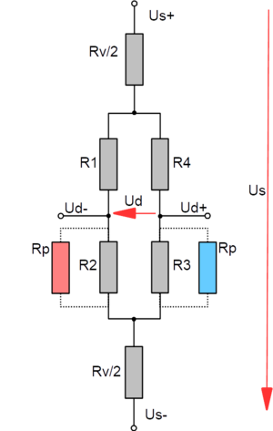
Another error is caused by additional series resistors. These can be, for example, the resistance of supply lines, or calibration resistors built in for the standard signal adjustment of sensors, and temperature-dependent nickel resistors built in for the drift adjustment of the E-module. The circuit diagram of the Wheatstone bridge with series resistors is shown in the following figure.
Bridge circuit with series resistor


