Call Us

We are ready to help

Request a special version

Didn't find what you were looking for?
This field cannot be empty.
This field must be at least 3 characters long.

Files

Drag & Drop files here or click to browse

File format supported: (.pdf, .zip, .docx, .png, .jpg .xlsx, .xls, .csv, .txt) & Max Filesize: 25mb

Need to be uploaded up 1 to 3 files.
File format supported: (.pdf, .zip, .docx, .png, .jpg .xlsx, .xls, .csv, .txt) & Max Filesize: 25mb
Leave your details so we can contact you
This field cannot be empty.
This field must be at least 3 characters long.
This field cannot be empty.
Please enter a valid email address.
This field cannot be empty.
Please enter a valid phone number.
This field cannot be empty.
Server error. Try again later.
Thank you!
We will send you a confirmation email and will contact you soon.
Don't have account yet? Register
Back to shopping

Multi-component sensor assembly

The multi-component sensor consists of a hexapod rod structure arranged between two plates without additional joints. The sensor is (usually) made of a single piece of high-strength aluminum (3.1354) or high-strength, ferritic stainless steel (1.4542).

For the sensor to function properly, it is crucial that the front surfaces are not locally deformed.

A local deformation is caused, for example, if a point-like force Fz is applied in the center of the sensor.

The force is introduced across the circular ring between the inner centering collar and the outer diameter. The force is introduced on the trapezoidal circular ring segments. The recesses between the segments are not loaded.

In addition to the force introduction on the circular ring, the flatness and rigidity of the connection flange are important parameters. The material should be high-strength aluminum or tool steel 24CrMo4 or C60 tempered or high-strength stainless steel 1.4542. Plastic flanges from the 3D printer are unsuitable!

A screw that is not tightened can cause measurement errors of the order of 10% or more.

The tolerance for the flatness of the flanges is 0.02mm.

Table 1 provides guidelines for the thickness of the connection flanges and the recommended tightening torque. If the recommended tightening torque exceeds the nominal torque of the sensor, no torque should be passed through the sensor. Instead, the flange should be held directly against the sensor.

The screws should have a strength of at least 8.8. From 100Nm, screws 10.9 are recommended.


Symmetry of the flange

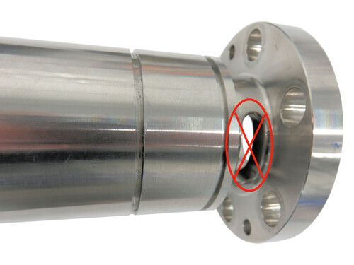
When designing the flange, care should be taken to ensure that local weak points do not cause asymmetrical deformation of the surface of the force sensor.

Individual outbreaks as shown in the adjacent figure should be avoided.

Mounting the flange

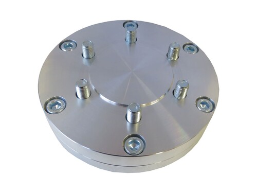
The assembly of all components from one side is often only possible by designing a two-part flange.

Example for K3D110:

Adapter for Comau SMART-5 NJ-60:

zb-k6d110_adaptation_000-a-.pdf

Flange for K6D80:

so051_001-a-.pdf

so051_002-a-.pdf

Force / moment introduction

When introducing forces and moments, care must be taken to ensure that the flange plates of the K6D sensor are not deformed. In particular, when introducing moments, the introduction should be central and symmetrical.

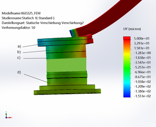
Flatness of the flange plate

The figure shows a local deformation of the flange plate due to an asymmetric introduction of a moment.

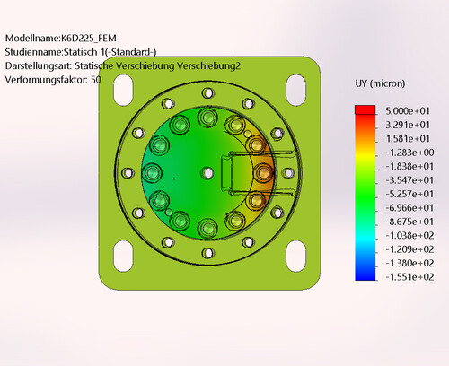
Symmetrical Introduction

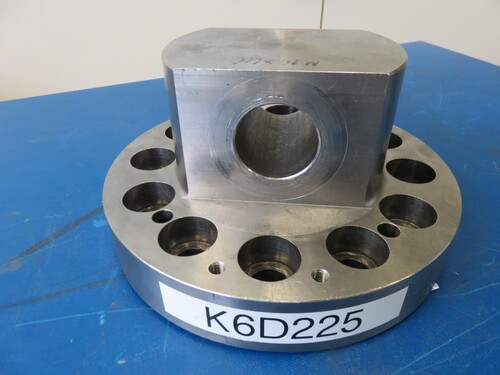
The figure shows a flange for the (largely) symmetrical introduction of moments for the K6D225 sensor.

Rules for mounting K6D sensors

  • High rigidity of the flange plate,
  • Good symmetry in the load / force introduction via the flange plate,
  • Low deformation within the sensor mounting surface <<10µm,
  • If these points cannot be achieved, then calibration of the sensor with the accessories is recommended.
  • Centering

  • The multi-component force sensors have a centering collar (inner diameter with 0...+0.1mm oversize, 1...3mm depth).
  • In addition, two pin holes with clearance fit E7/m6 are provided.
  • To secure the angular position, one of the following variants is recommended (depending on manufacturing tolerances):
    • Use of the centering collar to secure the centering plus 1 centering pin to secure the angular position in a slot
    • Use of 2 centering pins: in a hole E7 to ensure centering, and in a slotted hole to secure the angular position
    • Use of 2 centering pins in two holes E7 to ensure centering and angular position ("double fit")
    • Use of the centering collar and use of 2 centering pins in two holes E7 ("triple fit")
  • If double or triple fits are used, the use of centering pins DIN 7979 with internal thread is recommended if they are to be dismantled...
  • Materials

  • If possible, the flange should be made of the same material as the sensor: aluminum sensors with aluminum flange (approx. 23 µm/m/°C), steel sensors with steel flange (approx. 12 µm/m/°C). Otherwise, the temperature-related drift of the sensor can be negatively influenced by the introduction of temperature-related stresses.
     
  • Installation position

  • The sensors can be mounted in any position. As with any force sensor, care must be taken to ensure that the connecting cable is assigned to the fixed bank (the non-moving flange). Otherwise, forces will be introduced into the sensor via the connecting cable.
bars-filter