Call Us

We are ready to help

Request a special version

Didn't find what you were looking for?
This field cannot be empty.
This field must be at least 3 characters long.

Files

Drag & Drop files here or click to browse

File format supported: (.pdf, .zip, .docx, .png, .jpg .xlsx, .xls, .csv, .txt) & Max Filesize: 25mb

Need to be uploaded up 1 to 3 files.
File format supported: (.pdf, .zip, .docx, .png, .jpg .xlsx, .xls, .csv, .txt) & Max Filesize: 25mb
Leave your details so we can contact you
This field cannot be empty.
This field must be at least 3 characters long.
This field cannot be empty.
Please enter a valid email address.
This field cannot be empty.
Please enter a valid phone number.
This field cannot be empty.
Server error. Try again later.
Thank you!
We will send you a confirmation email and will contact you soon.
Don't have account yet? Register
Back to shopping

CAN bus basics

General introduction

Interfaces are used to transfer information between the individual components of a system.

In a bus system, all components are connected to a common data line via short spur lines.

This minimizes the amount of cabling required and additional components can easily be connected.

However, the data flow must be controlled via an access procedure (protocol) if all components use a common bus line. If possible, components

components from different manufacturers should work together.

The Controller Area Network (CAN) connects several equally authorized components (nodes) via a 2-wire bus plus an additional ground line. The CAN protocol was developed by Bosch in 1983 for use in motor vehicles and was first presented to the public in 1986.


Figure 1: Controller Area Network (CAN)

Due to its high interference immunity, low costs and real-time capability, CAN is not only used in the automotive industry, but also in many other sectors (e.g. in commercial vehicles, mobile machinery, railroads, medical technology, industrial automation, elevators and as a machine bus system).

The organization “CAN in Automation” (CiA) is dedicated to the further development of the CAN protocol and the specification of the CANopen application protocol as well as the CANopen profiles.

Physical description of the CAN interface

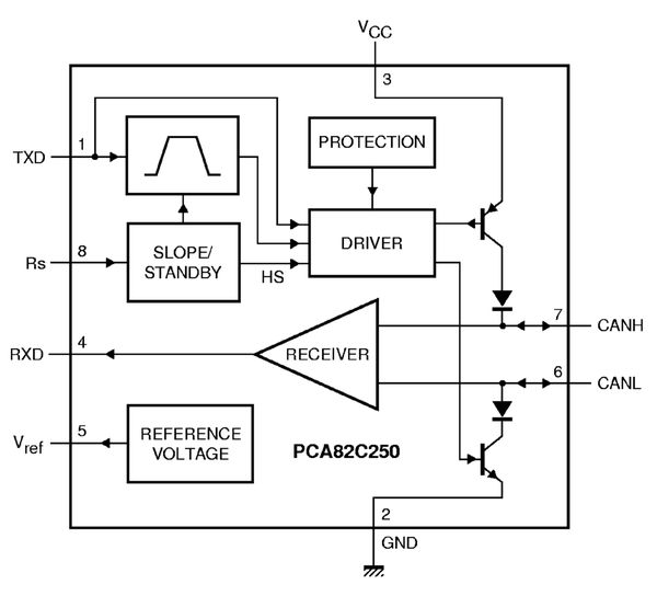
The physical CAN transmission is standardized in ISO 11898-2 (high-speed) and ISO 11898-3 (low-speed). Transceivers from various manufacturers are available to implement this specification, such as the PCA82C250 from NXP.

Electrical interference immunity is achieved, among other things, by mapping a bit on two lines simultaneously with a potential change in the opposite direction. This is also referred to as a differential signal.

This means that the logical signal is transmitted redundantly inverted on a second line.

Interference interspersed in the line acts on both lines in the same direction. However, as the two differential lines always have opposite levels, the difference in level is largely maintained even in the event of interference. This is called common mode rejection ratio (CMRR). The CAN-High and CAN-Low lines contain the inverted and non-inverted serial data signal.


The design as an open collector (PNP on VCC for CAN-H and NPN on GND for CAN-L) also means that several nodes can be connected in parallel on the bus without causing electrical short circuits in the event of a conflict.

The state with two different levels on CAN-H and CAN-L is referred to as the dominant state (level difference: 2.0 volts nominal); the state with two identical levels is referred to as recessive (level difference: 0.0 volts nominal).
The dominant state corresponds to a logical zero: If a node places a logical zero on the bus, it may overwrite the state of a logical one of another node. The coupling of the nodes via the bus line represents a logical AND link (Wired-And).

Figure 2: Transceiver PCA82C250 from NXP


logischer Pegel

Zustand

CAN-H

CAN-L

Differenzpegel

0

dominant

Transistor durchgeschaltet (zieht Pegel auf VCC)

Transistor durchgeschaltet (zieht Pegel auf GND)

2 Volt

1 oder hochohmig

rezessiv oder floating

Transistor gesperrt

Transistor gesperrt

0 Volt

Table 1: Representation of the logical levels in CAN

A further measure to increase interference immunity is NRZ coding, i.e. there is not an edge change in every bit. To prevent the participants from losing synchronization with the transmitter, the transmitter inserts a bit of the other polarity (bit stuffing) after five bits of the same “polarity” (recessive or dominant). The receivers automatically remove these stuff bits so that the bit sequence sent and the one forwarded to the host controller are identical.


Pin assignment

The 9-pin Sub-D connector proposed by CAN in Automation (CiA) has become established as the CAN connector in many applications. Both “female” and “male” connectors are used simultaneously in the nodes. This means that additional nodes can be integrated into the bus line without interruption. (“daisy-chain” wiring)

At least one 3-pole cable with CAN-High, CAN-Low and Ground is required for the transmission of CAN signals. The use of a shielded cable is not mandatory. For longer cable lengths, twisting of the cable pair and shielding are recommended.

CiA has also recommended the pin assignment for other connectors (CiA 303-1): for example, for the 5-pin M12 circular connector and 4- and 5-pin “open style” connectors, without going into the dimensions. Another useful feature is the 10-pin “multipole connector” defined by CiA, where pin 10 is reserved and must not be used.

PIN

Signal

Beschreibung

1


reserviert

2

CAN-L

negiertes CAN-Signal (Dominant Low)

3

CAN-GND

Masse

4


reserviert

5

CAN-SHLD

Schirmung (optional)

6

GND

Geräte Masse (optional)

7

CAN-H

positives CAN Signal (Dominant High)

8


reserviert

9

VCC

Versorgungsspannung (optional)

Table 2: CAN assignment of the D-SUB 9 connector 

Bit rate and cable lengths

In principle, the CAN network can transmit bit rates of up to 1 Mbit/s. All CAN nodes must be able to process the message simultaneously. The maximum cable length therefore depends on the bit rate. The table shows recommended bit rates and the corresponding maximum cable length.

The achievable length also depends on the cable used, the network topology and the sampling time.

Bitrate

Kabellänge

10 kbits/s

6,7 km

20 kbits/s

3,3 km

50 kbits/s

1,0 km

125 kbits/s

500 m

250 kbits/s

250 m

500 kbits/s

125 m

1 Mbits/s

25 m

Table 3: Relationship between CAN bit rate and maximum cable length

Bus termination (terminating resistor)

In the CAN bus, bus termination takes place with a line topology with 120 ohms at both ends of the network.

Termination is also recommended for short lines with low bit rates. Without termination, reflections occur. In practice, termination at one end is sufficient for short lines, but ideally the bus should be terminated at both ends (and only there) with 120 ohms each.

Principle of data exchange in the CAN network

During data transmission in a CAN bus, no nodes are addressed, but the content of a message (e.g. speed or engine temperature) is identified by a unique identifier. In addition to marking the content, the identifier also determines the priority of the message.

With the subsequent acceptance check, all stations use the identifier (ID) to determine whether the received data is relevant to them or not once the message has been received correctly. A high degree of flexibility is achieved through content-related addressing: stations can be added to the existing CAN network very easily.

All messages are heard by all stations (“broadcast”) and forwarded to the host controller for processing depending on the ID acceptance filtering. Measured variables that are required as information by several control units can be distributed via the CAN network so that not every control unit requires its own sensor.

Collision check

Each participant may send messages without a special request from another participant (e.g. master). As with Ethernet, it is possible for several participants to send simultaneously. The message with the lowest identifier (the lowest binary value) is given permission to send.

The process for collision checking via the identifier is called “bit-by-bit arbitration”. According to the “wired-and-mechanism”, in which the dominant state (logical 0) overwrites the recessive state (logical 1), all those nodes that transmit recessively but detect a dominant bit on the bus lose the competition for bus allocation. All “losers” automatically become recipients of the message with the highest priority and only attempt to transmit again when the bus becomes free.

Simultaneous bus access by several nodes must always result in a unique transmission permission, which is why the identifiers must be assigned uniquely, i.e. they must not be used by two nodes at the same time. The method of bit-by-bit arbitration via the identifiers of the messages waiting to be transmitted means that each collision is unambiguously resolved after a calculable time: for messages in basic format (11-bit ID) this is a maximum of 13 bit times (29-bit ID), in extended format it is a maximum of 33 bit times. The stuff bits mentioned above are not taken into account.

Layers of the CAN software and CAN hardware

The individual tasks of CAN communication are performed in “layers” according to the IOS/OSI reference model.

  • Bit transmission layer (physical layer): This layer describes the physical properties, such as signal level, transmission speed, sampling time, connector, cable, etc. It is partially realized in the CAN controller and in the CAN transceiver.
  • Transmission layer (data link layer): This is the actual CAN protocol with its message formats (data telegrams, remote request telegram, error telegram and overload telegram) as well as the error behavior (“fault confinement”).
  • The higher protocols: The layers above this are not usually specified individually and are normally implemented in software on the host controller. In some industries, these higher protocols are standardized (e.g. CANopen, DeviceNet, SAE J1939). The automotive industry has internationally standardized a transport protocol in ISO 15675, with which long messages with more than 8 bytes can be segmented on the sender side and reassembled on the receiver side.


Structure of a CAN message

A message is packaged in a form specific to the CAN bus. This packaging is referred to as a “frame”.

A frame consists of seven characteristic fields:

  • Start field (start-of-frame bit)
  • Arbitration field (CAN identifier plus RTR bit)
  • Control field (contains the data length code)
  • Data field (0 to 8 bytes)
  • CRC field (contains a 15-bit checksum and an end mark)
  • Acknowledge field (ACK bit plus end marker)
  • End field (end-of-frame)

There are two frame formats, which differ mainly in the length of the identifier:

  • Basic format (11-bit identifier)
  • Extendet format (29-bit identifier)

A distinction is made between the following types of frames:

  • Data frame (message is sent without a special request)
  • Remote Transmission Request (RTR) Frame (message is requested - the recipient who “owns” the message with the requested identifier delivers the corresponding data frame)
  • Basic frame according to ISO 11898-1 (formerly also referred to as CAN 2.0A):


Start

1 Bit

Identifier

11 Bit

RTR

1 Bit

IDE

1 Bit

r0

1 Bit

DLC

4 Bit

DATA

0...8 Byte

CRC

16 Bit

ACK

2 Bit

EOF+IFS

10 Bit


Extended frame according to ISO 11898-1 (formerly known as CAN2.0B):

Start

1 Bit

Identifier

11 Bit

SRR

1 Bit

IDE

1 Bit

Identifier

18 Bit

RTR

1 Bit

r1

1 Bit

r0

1 Bit

DLC

4 Bit

DATA

0...8 Byte

CRC

16 Bit

ACK

2 Bit

EOF+IFS

10 Bit


  • Start: dominant, used for synchronization,
  • Identifier: information for the receiver and priority information for bus arbitration,
  • RTR: distinguishes between data (dominant) and RTR telegram (recessive),
  •  
  • IDE: Identifier Extension,
  • r0, r1: reserved,
  • DLC: contains the length information of the subsequent data field,
  • DATA: contains the data of the telegram,
  • CRC: contains the CRC checksum and the CRC end identifier for the preceding bit sequence,
  • ACK: contains an acknowledgement from other participants when the message has been received correctly,
  • EOF: indicates the end of the data telegram (seven recessive bits),
  • IFS: 3-bit long space between CAN frames,
  • SRR: replaces the RTR bit in the extended frame,
  • IDE: indicates that a further 18 bits follow,


Error detection in the CAN network

The CAN protocol can detect and signal errors itself. To detect errors, three mechanisms are implemented in the CAN protocol at message level:

1. cyclic redundancy check (CRC)

The CRC secures the information of the frame by adding redundant check bits on the transmitting side. On the receive side, these check bits are recalculated from the received bits and compared with the received check bits. If they do not match, there is a CRC error.

2. frame check

This mechanism checks the structure of the transmitted frame. The errors detected by the frame check are referred to as format errors.

3 ACK error

The frames received are acknowledged by all receivers with a positive acknowledgement (the recessive bit of the sender is “overwritten” by dominant bits of the receivers). If no acknowledgement is recognized at the transmitter (ACK error), this indicates a transmission error that may only be recognized by the receivers, a falsification of the ACK field or non-existent receivers.

The CAN protocol also implements two mechanisms for error detection at bit level.

1. monitoring

Each node that transmits simultaneously monitors the bus level. It recognizes differences between transmitted and received bits. This means that all global errors and bit errors occurring locally at the transmitter can be reliably detected.


2. bit stuffing
The coding of the individual bits is checked at bit level. The CAN protocol uses NRZ coding (non-return-to-zero), which ensures maximum efficiency in bit coding. The synchronization edges are generated using the bit-stuffing method, whereby the transmitter inserts a stuff bit with a complementary value into the bit stream after five consecutive bits of equal value, which the receivers automatically remove again. If one or more errors are detected by at least one node using the mechanisms described above, the ongoing transmission is aborted by sending an “error flag”. This prevents other stations from accepting the transmitted message and thus ensures network-wide data consistency. After aborting the transmission of an erroneous message, the sender automatically begins to send its message again (Automatic Repeat Request).
If an error occurs several times in succession, the node is automatically switched off.

Effective transmission rate for data bytes

Despite the automatic access of a CAN node to the bus line, reference values for the effective transmission rate can be specified for a node with the highest priority. A message in basic format with eight data bytes requires a maximum of 130 bits. This is based on a maximum number of 19 stuff bits and 3 space bits:

1 start bit

+11 identifier bits

+ 1 RTR bit

+ 6 control bits

+ 64 data bits

+ 15 CRC bits

+ 19 (maximum) Stuff bits + 1 CRC d

elimiter

+ 1 ACK slot

+ 1 ACK delimiter

+ 7 EOF bits

+ 3 IFS (Inter Frame Space) bits

= 130 bits

A maximum of 154 bits can be transmitted in extended format.

The net data rate is calculated by dividing the number of data bits by the total number of bits times the transmission rate.

The following table lists reference values for the effective transmission rate for different numbers of data bytes. The variable number of stuff bits is not taken into account:


effektive Übertragungsrate in kBit/s

bei 1000 kBit/s

Anzahl Datenbytes pro Frame

mit Standard ID

mit Extended ID

1

145

107

2

254

193

3

338

264

4

405

323

5

460

374

6

505

417

7

432

455

8

576

489

Table 4: Effective transmission rates
The GSV-3CAN measuring amplifier, which transmits one measured value with three data bytes per frame, can transmit a maximum of 338*1024/24 = 14421 measured values per second via the CAN network at 1 MBit/s.
In the packed format of the GSV-3CAN, on the other hand, a frame with 8 data bytes is used, which contains four measured values of two bytes each.
This increases the number of measured values that can be recorded via the CAN network to 576*1024/64*4 = 36864 per second.

Measuring amplifier with CAN for strain gages

For the evaluation of signals from strain gages, the measuring amplifiers

measuring amplifiers GSV-2, GSV-3, GSV-6 and GSV-8 are available.

Produkt Beschreibung
GSV-2LS Leiterplatte; RS232 und CAN, CANopen Protokoll;
GSV-2AS IP66 Alu Gehäuse, RS232 und CAN, CANopen Protokoll;
GSV-2FSD Fronttafel Einbau; Display, RS232 und CAN, CANopen Protokoll;
GSV-2TSD-DI Desktop Gerät mit Akku; Display, RS232, USB und CAN, CANopen Protokoll;
GSV-3CAN IP66 Alu Gehäuse, CAN
GSV-6CPU Leiterplatte, 3.3V, UART und CAN, jeweils ohne Transceiver
GSV-8DS Desktop  8-Kanal Messverstärker; UART, USB, CAN mit CANopen Protokoll
GSV-8AS IP66 Alu Gehäuse, 8-Kanal Messverstärker; UART, USB, CAN mit CANopen Protokoll

Table 5: Measuring amplifier for strain gauges with

CAN Further links

http://www.can-cia.org/ CAN in Automation (CiA) ist die internationale Anwender- und Herstellervereinigung für das Controller Area Network (CAN).


bars-filter