Call Us

We are ready to help

Request a special version

Didn't find what you were looking for?
This field cannot be empty.
This field must be at least 3 characters long.

Files

Drag & Drop files here or click to browse

File format supported: (.pdf, .zip, .docx, .png, .jpg .xlsx, .xls, .csv, .txt) & Max Filesize: 25mb

Need to be uploaded up 1 to 3 files.
File format supported: (.pdf, .zip, .docx, .png, .jpg .xlsx, .xls, .csv, .txt) & Max Filesize: 25mb
Leave your details so we can contact you
This field cannot be empty.
This field must be at least 3 characters long.
This field cannot be empty.
Please enter a valid email address.
This field cannot be empty.
Please enter a valid phone number.
This field cannot be empty.
Server error. Try again later.
Thank you!
We will send you a confirmation email and will contact you soon.
Don't have account yet? Register
Back to shopping

1. filter function of the measuring amplifier

The output signal of a force sensor or strain gauge is made up of static components (DC voltage components) and dynamic components (vibrations or rapid, pulse-like signal changes).

The static component can be, for example, the weight on a load cell; dynamic components result, for example, from shock-like loads when a weight is applied.

Other causes of dynamic loads are, for example, vibrations of the system with the natural frequency of the load cell and mass (“mechanical spring” and “weight”).

Unwanted dynamic components are, for example, interferences of e.g. 50Hz or 100Hz from other electrical devices or from cables laid parallel to the sensor cable. The amplifier electronics themselves also generate dynamic components (noise with a large number of frequency components (“white noise”).

The task of the low-pass filter is to remove the dynamic components in the output signal in order to allow only the desired frequency components to pass. By limiting the so-called “bandwidth”, the resolution is improved, e.g. by filtering oscillations and transmitting only the “static” part of a scale.

The more dynamic components a signal contains, the greater the noise amplitude. As a rule of thumb: 10 times the bandwidth means 3 times the noise amplitude (√10 times for white noise, to be precise).

Therefore, the bandwidth of the measuring amplifier should be selected “as low as possible” and “as high as necessary”.

2 Cut-off frequency of the low-pass filter

At the cut-off frequency fg, the signal amplitudes are attenuated by 3dB (to approx. 70% amplitude compared to static signals).
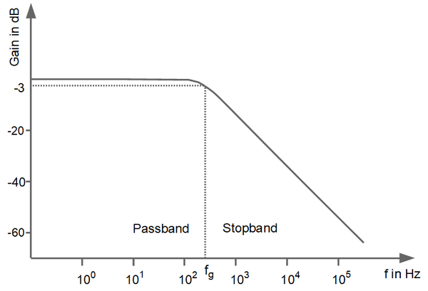
Abb. 1: Frequenzgang eines Tiefpassfilters

3 Analog measuring amplifiers

In the analogue measuring amplifiers GSV-1, GSV-5 and GSV-11, the filter is implemented as a second-order active filter with Bessel characteristic.

The attenuation is approx. 40 dB per decade, i.e. in the stop band the amplitude of a signal component with ten times the frequency is reduced by a factor of 100.

Design of analog measuring amplifiers.

The cut-off frequency is set using different resistors and capacitors. In addition to the active low-pass filter in the output stage of the measuring amplifier, there are other influencing factors that cause a limitation of the bandwidth. These include, for example, the gain-bandwidth product of the differential amplifier in the input stage of the measuring amplifier, but also components for EMC in the input stage, such as chokes and protective diodes.

Table 1 provides an overview of the available bandwidths with GSV-1, GSV-5 and GSV-11:


Typ Grenzfrequenz Rauschamplitude max-min Auflösung
(2mV/V / Rauschamplitude)
GSV-11H 010/20/2 20 Hz 200 nV/V 10000
GSV-11H 010-5/20/2 20 Hz 200 nV/V 10000
GSV-11H 4-20/20/2 20 Hz 200 nV/V 10000
GSV-11H 4-20-12/20/2 20 Hz 200 nV/V 10000
GSV-1H 010/250/2 250 Hz 100 nV/V 20000
GSV-1H 010/2k5/2 2,5 kHz 300 nV/V 7000
GSV-1H 010/10k/2 10 kHz 600 nV/V 3000
GSV-1A8 2,5 kHz 300 nV/V 7000
GSV-1A4 250 Hz 300 nV/V 7000
GSV-5L 250 Hz 250 Hz 100 nV/V 20000
GSV-5L 2.5 kHz 2.5 kHz 300 nV/V 7000
GSV-5L 10 kHz 10 kHz 600 nV/V 3000


4 Measuring amplifier with digital signal processing

4.1 Measuring amplifier with (configurable) analog output

The GSV-15L, GSV-6L, GSV-6K and GSV-13i measuring amplifiers (exclusively) have an analog output. The signal from the force sensor or the strain gauge is digitized with an analogue/digital converter, processed in a microprocessor and output as a digitally scaled and digitally filtered signal with a digital/analogue converter.

The input signal is digitized at the sampling rate. The output signal is updated via the D/A converter at the data frequency.

Messverstärker Samplingrate

Datenfrequenz am Analogausgang

Rauschamplitude max -min bei 2 mV/V Messbereich Auflösung 2 mV/V / Rauschamplitude
GSV-15L 315 S/s 315 Hz 300 nV/V 7000
GSV-6L, GSV-6K 25 kS/s 10 Hz ... 25 kHz kundenseitig konfigurierbar (mit ClickRClackR) 300 nV/V bei 10Hz 7000
GSV-13i / GSV-13q 25 kS/s 10 Hz 600 nV/V 3000
GSV-8 bis 8x 48 kS/s simultan (Summenabtastrate 384 kS/s) 1 Hz ... 16 kHz kundenseitig konfigurierbar (mit GSVmulti);

20 nV/V bei 10Hz digital

100 nV/V bei 10Hz analog

100000 digital

20000 analog

4.2 Digital measuring amplifiers with non-configurable analog output

The GSV-2LS, GSV-2AS, GSV-2FSD-DI and GSV-2TSD-DI measuring amplifiers have a special position. In addition to an interface (USB or RS232 or CANbus), these measuring amplifiers have an analog output that is fed to an analog, non-scalable output stage before the A/D converter. Only an automatic zero adjustment is possible.

The analog output of the GSV-2 corresponds to the analog output of the GSV-1. The GSV-1 is suitable for predominantly analog applications; the GSV-2 is suitable for predominantly digital applications.

4.3 Digital measuring amplifier with (configurable) analog output and configurable digital filters

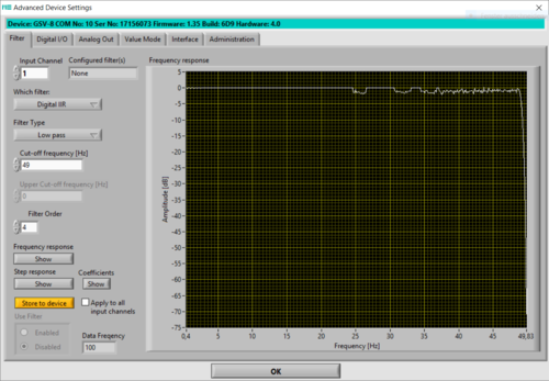
The GSV-8 measuring amplifier has digital filters FIR up to 14th order and IIR up to 4th order. Configuration is possible with the GSVmulti software. With the IIR filter, the characteristics “low pass”, “high pass”, “band pass”, “band stop” can be realized at the analogue output, with the FIR filter low pass filters up to 14th order are realized.

4.3.1 Configuring the data frequency

The following also applies to the data frequency setting: as low as possible, as high as necessary. When the data frequency is set, continuous mean value filtering is automatically activated. This filters out high-frequency interference components.

The data frequency must be set sufficiently high if, for example, sudden signal changes and peak values are to be recorded. In theory (Nyquist-Shannon sampling theorem), the data frequency must be at least twice the signal frequency. In practice, setting a data frequency that is 5 to 10 times the signal frequency has proven successful.

When the data frequency is configured, an analog low-pass filter is automatically activated in the GSV-8, which is connected upstream of the A/D converter as an anti-aliasing filter.

4.3.2 Configuration of additional IIR and FIR filters

The GSV-8 series measuring amplifiers allow the configuration of digital filters. Setting digital filters requires expert knowledge of digital filter technology. The setting of digital filters can be useful, e.g. to implement a bandstop or a bandpass filter. For the design of digital filters, especially fourth-order digital IIR filters, software tools or simulation software, such as Matlab, are generally used for a fee. Experts in filter technology will find the GSVmulti software a useful tool for designing a fourth-order IIR filter.


5 Konfiguration des digitalen Filters

For experts:

With the GSV-8, individual filter characteristics can be configured for the 8 measuring channels.

https://www.me-systeme.de/forum/post653.html?hilit=filter#p641

https://www.me-systeme.de/forum/post653.html?hilit=filter#p653


bars-filter