Call Us

We are ready to help

Request a special version

Didn't find what you were looking for?
This field cannot be empty.
This field must be at least 3 characters long.

Files

Drag & Drop files here or click to browse

File format supported: (.pdf, .zip, .docx, .png, .jpg .xlsx, .xls, .csv, .txt) & Max Filesize: 25mb

Need to be uploaded up 1 to 3 files.
File format supported: (.pdf, .zip, .docx, .png, .jpg .xlsx, .xls, .csv, .txt) & Max Filesize: 25mb
Leave your details so we can contact you
This field cannot be empty.
This field must be at least 3 characters long.
This field cannot be empty.
Please enter a valid email address.
This field cannot be empty.
Please enter a valid phone number.
This field cannot be empty.
Server error. Try again later.
Thank you!
We will send you a confirmation email and will contact you soon.
Don't have account yet? Register
Back to shopping

Selecting the right sensor

The selection of the appropriate force-torque sensor is initially based on the measuring ranges for the forces and moments in the three coordinate axes.

Other boundary conditions include geometry, installation conditions, accuracy, weight, and stiffness.

This article is intended to help you make the right decision when selecting a sensor. Our sales staff will be happy to assist you in selecting the right sensor based on the specific application conditions.

Selection of the measuring range

The measuring range is the primary factor in the selection: The force/torque sensor (6D sensor) must not be used above its so-called operating forces and operating moments. Above these forces or moments, the sensor can be destroyed by plastic deformation. The measurement signals then lie outside the range that can still be evaluated by the measurement electronics.

A special feature of force/torque sensors is, unlike 1D force or torque sensors, that the operating forces and moments are often not in the order of 150% to 200% of the measuring range, but usually up to 300% of the measuring range.

The document k6d-comparisontable-de-en.pdf provides a very good overview of operating forces.

With 6D sensors, additional safety against overload usually does not need to be planned. On the contrary, the deliberate exceedance of individual force or torque components can be factored in.

In addition to the operating forces and moments, the resolutions are also specified. Resolution is defined as the noise amplitude at a measurement frequency of 10 Hz.

Consideration of the operating point

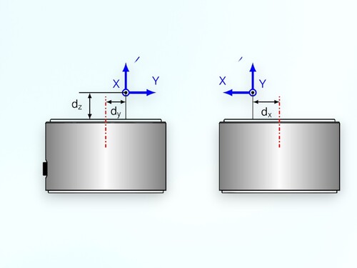
The forces are usually applied at a certain distance from the sensor's face (from the "origin of the force sensor"). This distance (usually in the positive z-direction) can be, for example, 50 mm to 1000 mm. If a force of, for example, 1 kN acts on the sensor at a distance of, for example, 100 mm from the face, a moment of 100 Nm must be considered when selecting the sensor.

Selecting the Sensor

Another selection criterion for force-torque sensors is the diameter of the sensor: The diameter should be as large as possible.

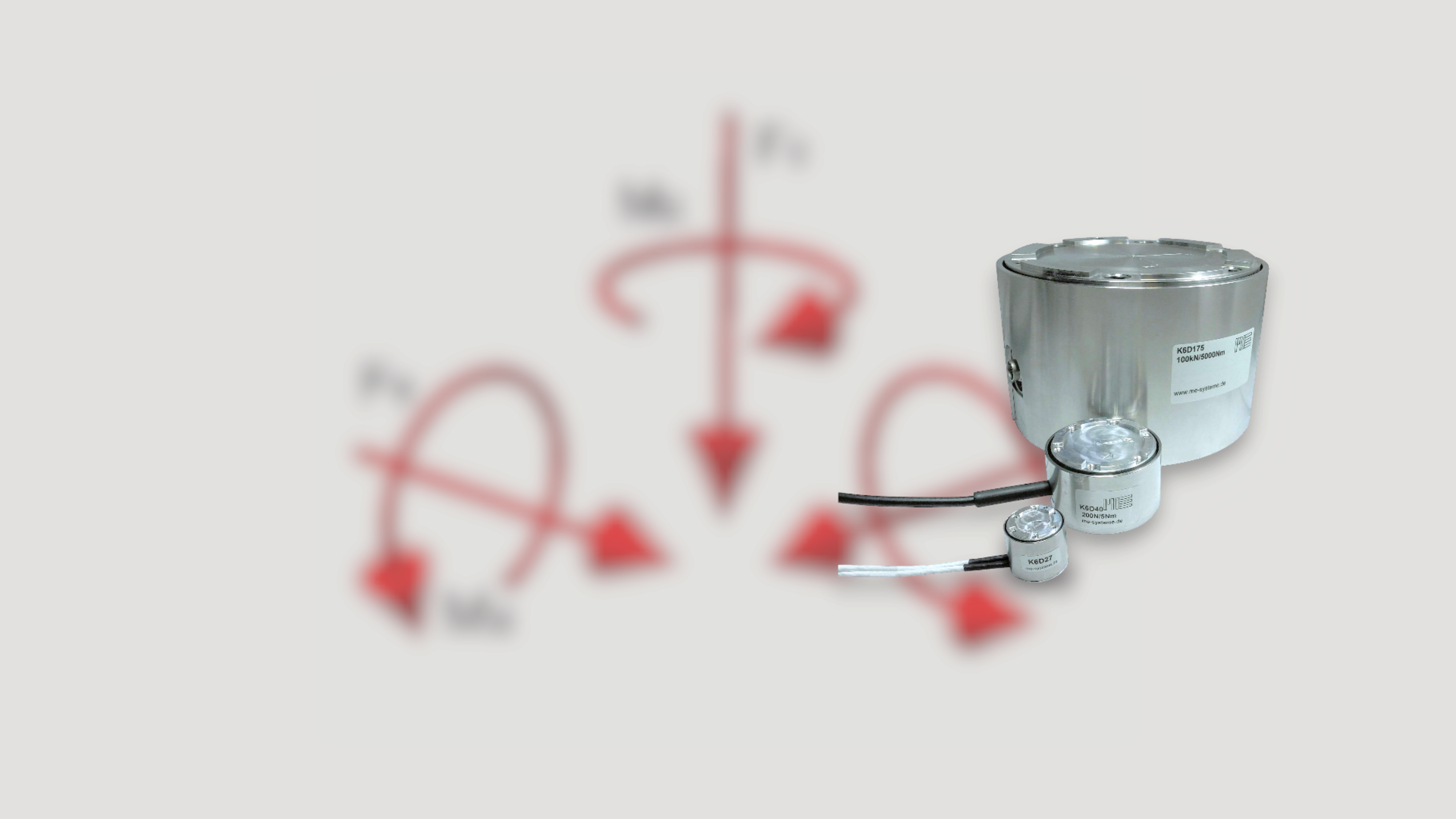
Therefore, if you have to choose between the K6D27 and K6D40, the sensor model with the larger dimensions should be selected.

This rule can be applied accordingly to all other models K6D80, 110, 130, 150, 175, 225, and 300.

The measuring ranges of the 6D sensor for the torques are essentially determined by the diameter of the 6D sensor. By selecting a larger diameter, the crosstalk of torques on the force signal display can usually be reduced.


Consideration of the installation situation

The highest accuracy with a 6D sensor is achieved when forces are applied in the area of ​​the sensor's face up to a distance of approximately 1x the diameter of the face.

As the distance of the force application from the face increases, the signal pattern becomes less defined, because a superposition of forces and moments is always introduced into the 6D sensor.

The sensor's mounting is subject to particularly stringent requirements: Local deformations of the force application flanges inevitably lead to measurement errors. The thickness of the counterflanges must be selected to avoid local deformations as much as possible. Recommendations for the minimum thickness of the flange plates are provided on the k6d-montage page. If even just one of the usually six fastening screws is not tightened or even not used, a measurement error will occur. Local deformations of the flange plates can occur, particularly when moments are introduced. Care must be taken to ensure that the flanges are as symmetrical as possible.

If this is not possible, calibration under the specific installation situation may be necessary.

Calibration at the operating point

For distances of 1 x diameter and above, calibration "at the operating point" may be appropriate. In this case, the calibration matrix is ​​calculated in the specific application, i.e., with superimposed moments. Crosstalk can be reduced in this case. Calibration at the operating point requires either specially adapted fixtures or it can be performed on a calibration machine that can simultaneously introduce all forces and moments.

Consideration of the load vector

The calibration matrix of the 6D sensor represents the relationship between the sensor's 6 (or 12) output signals and the applied forces and moments. The best possible calibration matrix is ​​determined from approximately 100 to 300 different load combinations using a compensation calculation. The closer the load vectors during calibration correspond to the actual application, the smaller the error.

Individual forces or moments are often applied in the subsequent application at only a fraction of the nominal forces and moments of the 6D sensor. Calibration with, for example, 10% of the nominal load of the 6D sensor is easily possible.

Due to the high resolution/low noise amplitude of the GSV-8 measuring amplifier, partial load does not reduce accuracy.

However, the relative temperature-related drift of the sensor is related to the nominal loads of the sensor. If the drift is related to the partial load of e.g. 10%, the relative drift increases accordingly by a factor of 10.

bars-filter